
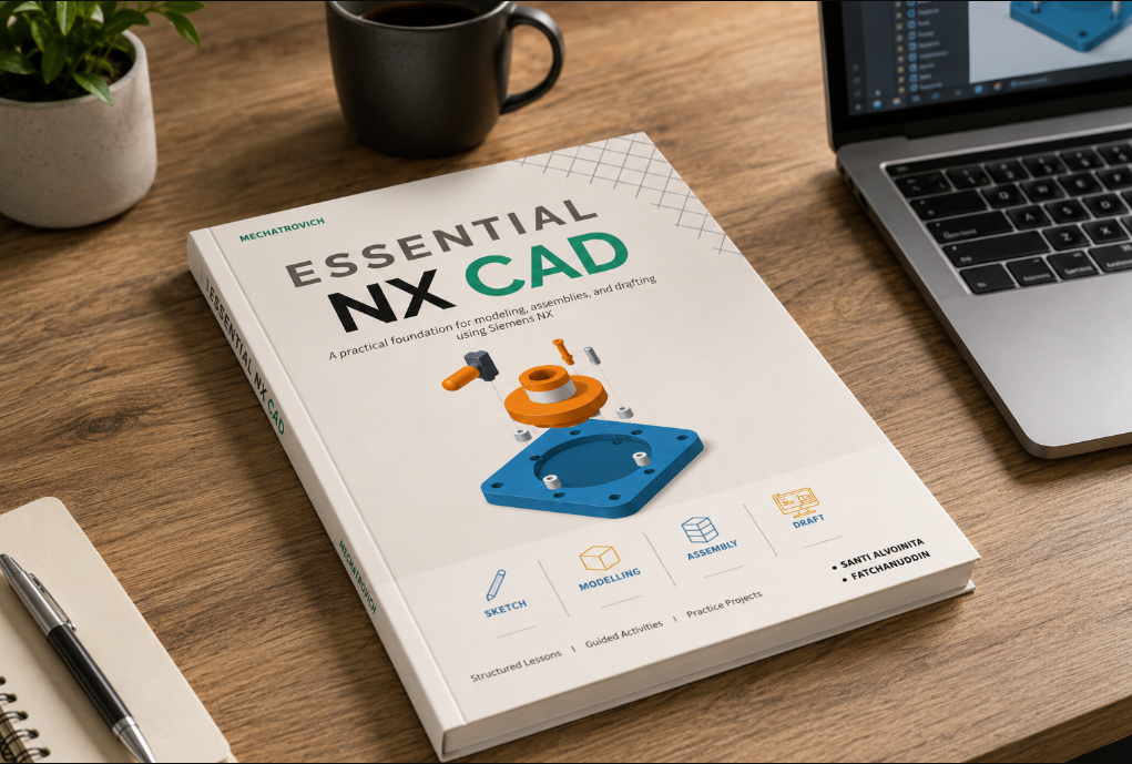
Most NX material can show where a button is. The harder—and more useful—skill is understanding what should happen before and after that command.
A new user rarely struggles because Extrude is impossible to find. The real difficulty is knowing which plane should carry the sketch, which dimensions should control the design, when a datum is necessary, how the feature should respond to a change, and how the finished model will later be assembled or documented.
This guide is organized around that connected workflow. Commands remain important, but each one is introduced as part of a design decision rather than as an isolated definition.
From an empty part file to a communicated design
The central NX workflow can be understood as five linked stages. Each stage produces an input for the next one, so weak choices early in the model usually reappear later as unstable features, difficult assembly constraints, or drawings that are hard to maintain.
The guide continues into freeform surface tools where simple solid features are no longer enough, then closes with practice projects that combine the sequence.
What a beginner actually needs to understand
Learning the interface matters, but interface familiarity should quickly become design reasoning. Four ideas make the individual commands easier to place.
The interface is a map
The Ribbon, Resource Bar, Part Navigator, graphics window, and status line tell you where work happens and what NX expects next.
A sketch is a design contract
Dimensions and constraints declare the relationships that should survive when the product changes—not only the shape visible today.
Features tell the model’s story
A readable feature sequence makes the part easier to inspect, modify, troubleshoot, and hand over to another engineer.
The drawing is not an afterthought
Modeling choices should anticipate assembly references, view orientation, manufacturing dimensions, and design communication.
Connect command behavior to design intent.
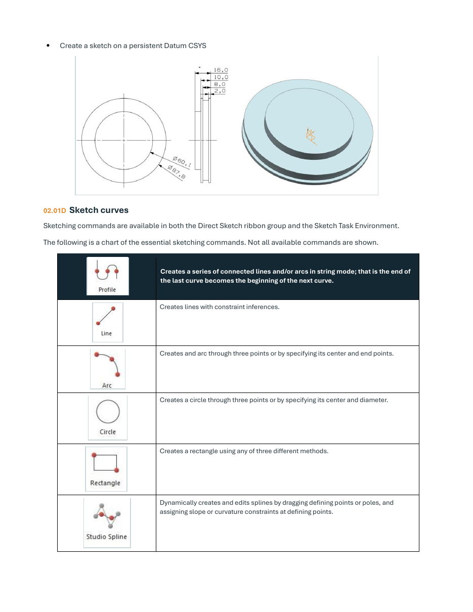
The lesson pages mix interface guidance, geometry examples, constraint behavior, and short procedures so the reader can understand both the action and its purpose.
- Inferred and applied constraints
- Dimensional control
- Degrees of freedom
- Curve tools and sketch strategy
One workflow, six structured lessons
The book starts with orientation, moves through the core parametric workflow, and then extends into assemblies, drawings, and freeform geometry. The structure lets a learner work from start to finish or return to a specific topic during design work.
NX environment & part setup
Sessions, templates, applications, the Ribbon, Roles, visibility, and essential NX terminology.
Sketching & design intent
Sketch planes, curve tools, inferred constraints, dimensions, and geometric constraint types.
Part features
Datums, extrude, revolve, sweep, holes, patterns, Boolean operations, shells, blends, and face edits.
Assembly relationships
Top-down and bottom-up approaches, components, the Assembly Navigator, movement, and constraints.
Drafting & documentation
Drawing sheets, base and projected views, dimensions, notes, sections, details, and associative updates.
Freeform modeling
Offset and bridge curves, extracted geometry, through-curve meshes, swept surfaces, sewing, and thickening.
See the material before deciding if it fits
The page design deliberately separates lesson orientation from detailed instruction. Each lesson opens with the outcome and topic map; the following pages then explain the commands, show the geometry, and provide the procedure.
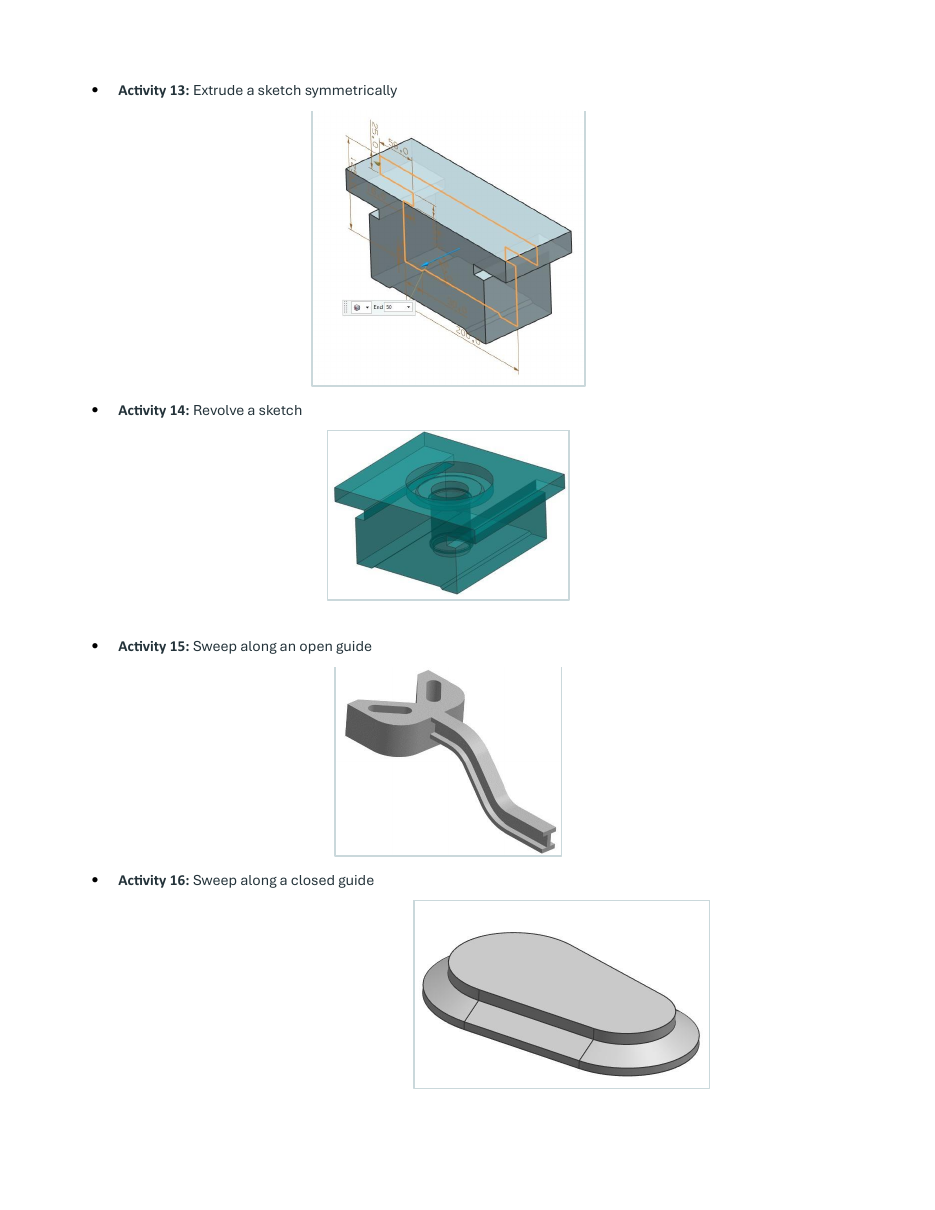 Part featuresExtrude, revolve, sweep, and feature decisions
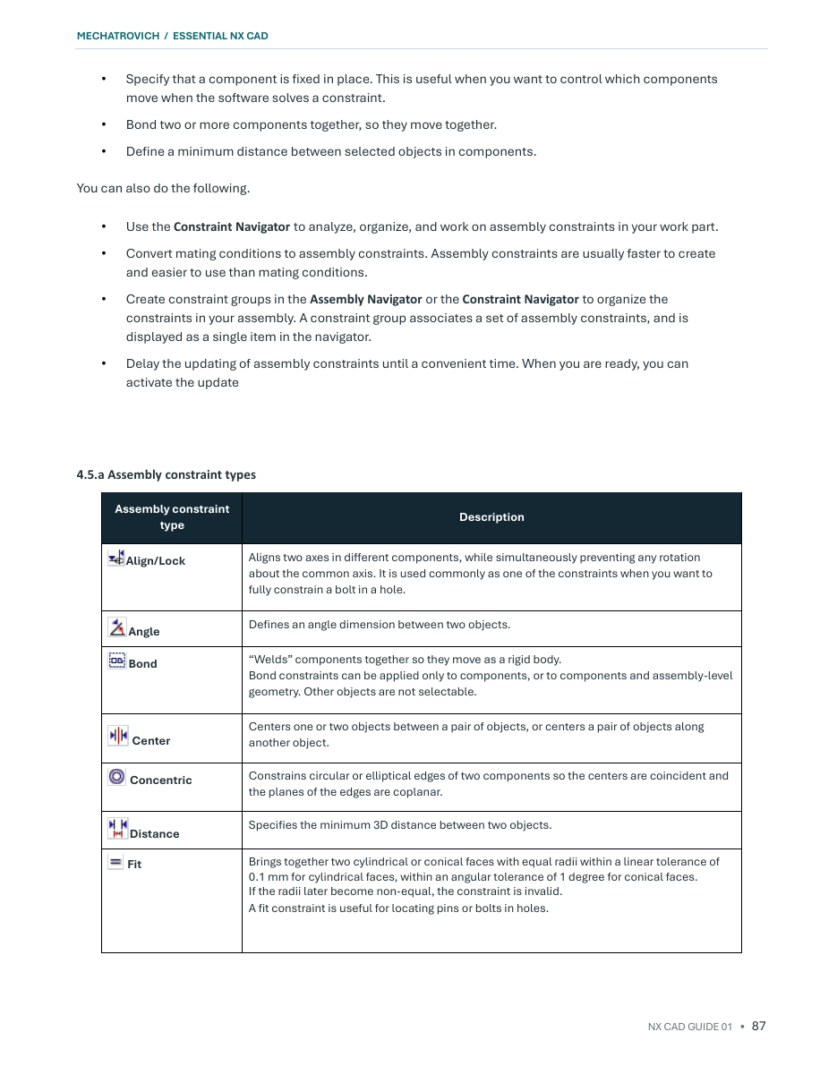 AssemblyComponents, movement, and constraints
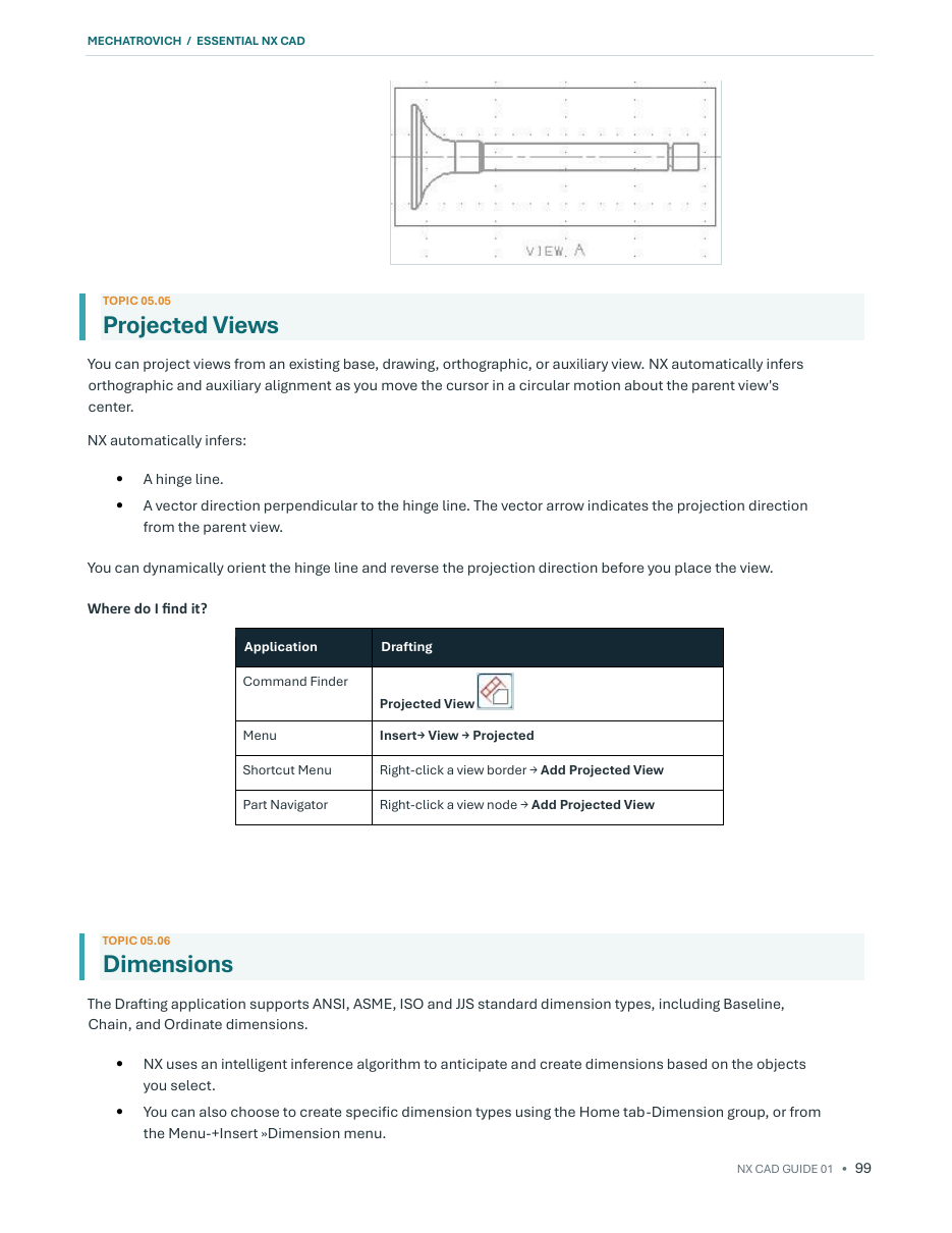 DraftingProjected views, dimensions, and drawing output
Selected pages from the current 153-page edition. The full book also includes detailed topic pages and freeform modeling coverage.
Practice turns reference material into capability
Reading explains the tools; recreating a part exposes whether the workflow is understood. The final section contains ten dimensioned exercises that require the reader to interpret geometry, choose a modeling sequence, build the part, and check the result.
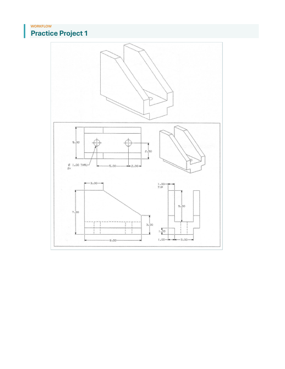
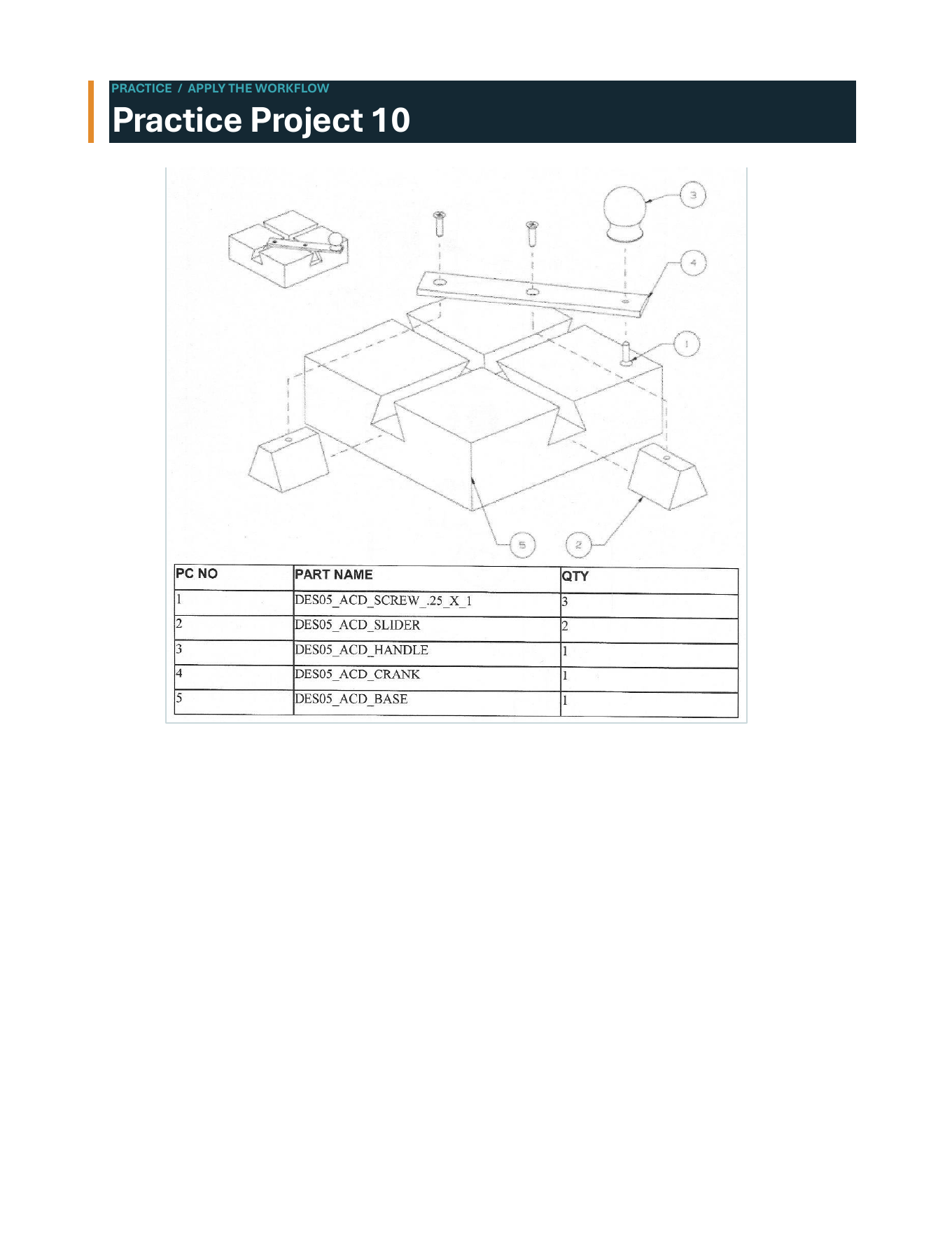
The projects are not presented as a single “correct click sequence.” The learner must translate the drawing into a feature plan—closer to the decision-making required in real CAD work.
Who this guide is—and is not—for
A useful fit
- Engineering students beginning with NX
- CAD users transitioning from another platform
- Junior engineers who need a structured reference
- Working users who want a visual refresher beside NX
Not a replacement
- Official Siemens documentation or certification
- Company-specific modeling and release standards
- Advanced specialist training in every NX application
- Engineering judgement about design and manufacture