
The project asked a straightforward control-engineering question: can the humidity inside a small aeroponic prototype be regulated by measuring relative humidity and changing the airflow that carries nutrient mist into the plant chamber?
The prototype used an ultrasonic mist maker to generate fine droplets, a DC fan to move the mist, and a DHT11 sensor as the humidity feedback device. A proportional–integral controller calculated the fan command from the difference between measured humidity and the chosen reference. The project note reported a working sensor range of approximately 65–90% RH, PI parameters of Kp = 2.22 and Ti = 280, and steady-state errors at three reference values.
Project video and prototype views
The project is documented with a working-prototype video and visual references of the physical setup and system concept. These help connect the control diagram and recorded controller values to the actual hardware used in the experiment.
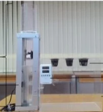
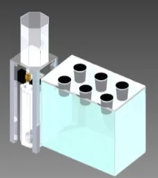
The control problem behind the project
Aeroponics supplies water and dissolved nutrients to exposed roots without soil. In the project, the root-zone environment was treated as a small chamber whose humidity could be influenced by moving atomized nutrient mist into it. The project used approximately 80% RH and 23°C as design context for the prototype, but those values should be read as project assumptions rather than universal crop specifications.
The controlled variable was humidity. The mist maker created the moisture source, while the fan became the actuator used by the controller. This distinction matters: the controller was not directly changing the chemistry of the nutrient solution or the mist-maker power. It was changing how much mist-laden air was transported into the chamber.
Humidity measurement and the DHT11
The project record states that the DHT11 was checked for linearity and was used successfully across the operating region from roughly 65% to 90% RH. For a student-scale prototype, the DHT11 was attractive because it combined humidity sensing, temperature sensing, internal signal conditioning, and a digital interface in a low-cost package.
From a control perspective, however, the important question is not simply whether a sensor produces a number. The sensor becomes part of the dynamic loop. Its accuracy, resolution, update rate, placement, and response time can all influence the apparent process response and therefore the controller tuning.
The sensor must cover the complete expected operating region with enough resolution to distinguish meaningful changes around the setpoint.
A sensor placed directly in the mist plume can report a different condition from a sensor placed near the roots or exhaust path.
A slow humidity response adds lag to the loop. Aggressive PI gains can then create overshoot or oscillation.
Direct wetting is not the same as measuring equilibrium air humidity and can distort the measurement.
Why the fan was used as the actuator
The ultrasonic mist maker generated the aerosol continuously or according to its own operating logic. The DC fan transported that aerosol into the controlled chamber. By changing fan speed, the system changed the rate at which moist air entered and circulated through the root-zone space.
In the project implementation, the fan was driven from the controller through PWM-based motor control. Increasing the command increased airflow; reducing the command reduced transport. The actual relationship between PWM duty cycle, motor speed, airflow, and resulting humidity was not perfectly linear, which is typical of small fan systems. Motor dead zones, driver voltage drop, chamber restriction, mist density, and back pressure all influence the process gain.
What the PI controller was doing
The controller compared the reference humidity r(t) with measured humidity y(t). Their difference formed the control error:
e(t) = r(t) − y(t)Proportional action reacts immediately to the present error. Integral action accumulates the error over time so that a persistent offset continues to change the actuator command until the error is driven closer to zero.
u(t) = Kp · e(t) + Ki ∫ e(t)dt with Ki = Kp / TiThe project reported Kp = 2.22 and Ti = 280. Using the common ideal-form relationship, this corresponds to an integral coefficient of approximately 0.00793 per unit of the time base used in the implementation. The available project documentation does not contain enough information to reconstruct the exact tuning procedure or sampling interval, so those values should remain identified as the recorded settings of that prototype—not transferable design constants.
A larger proportional gain normally makes the controller react more strongly to the current error, while stronger integral action removes persistent offset faster. Both can also make the loop more oscillatory if the sensor, fan, chamber, and moisture transport contain significant delay.
Recorded steady-state results
The project record reported three reference tests. The values below are preserved as project results rather than recomputed from missing raw time-series data.
| Humidity reference | Reported steady-state error | Engineering reading |
|---|---|---|
| 84% RH | 0% | The final measured value matched the stated reference within the reported resolution. |
| 86% RH | 2.3256% | A residual offset remained at this test point, suggesting setpoint-dependent process behavior, disturbance, sensor resolution, or tuning limitations. |
| 90% RH | 0.573% | The loop approached the requested reference with a smaller residual error than at 86% RH. |
Steady-state error is only one aspect of controller performance. Without the response curves, rise time, overshoot, settling time, oscillation amplitude, and disturbance-rejection behavior cannot be evaluated from these three numbers alone. A controller can have low final error and still respond too slowly or overshoot badly.
It supports the conclusion that the prototype could move humidity toward several commanded references with the recorded PI settings. It does not establish universal agronomic suitability, controller robustness, repeatability across hardware builds, or performance under changing reservoir level, root mass, temperature, or airflow restriction.
How the same experiment could be strengthened today
- Record the complete time response. Plot humidity reference, measured humidity, and fan command on the same time axis for every test.
- Define the sampling interval. PI tuning depends on how often the controller is evaluated and how the integral term is implemented digitally.
- Add actuator limits and anti-windup. If the fan reaches 0% or 100% command, the integral term should not continue accumulating without control.
- Characterize the fan. Measure PWM duty cycle versus RPM or airflow so the actuator nonlinearity is visible.
- Evaluate sensor dynamics. Compare the DHT11 against a reference instrument and estimate its response delay in the actual chamber.
- Test disturbances. Open the chamber, change the mist supply, or alter airflow restriction and observe recovery.
- Repeat each setpoint. Replication separates one successful run from consistent system behavior.